After the engine was installed, I noticed that the A/C compressor was quite close to the driver's shock tower. So close that the hose block that bolts onto the rear of the compressor would not fit. I had touched on this subject in an earlier post. Anyway, since I don't want to cut into the shock tower, that leaves me with a need for a new compressor. The 95' Mustang uses a York compressor mount. A friend told me about a Sanden compressor that has the hose in/out ports on the top. There is also an adapter plate that allows the Sanden to bolt onto the York mount. This seems like the best way to go.
I powered up the PCM and started testing circuits and relays. So far, each sensor plug and relay has the expected voltage. Now I am waiting for parts to arrive so I can continue the work.
More to come...
Tuesday, September 22, 2009
Saturday, September 19, 2009
Too Quick To Give Up
Once I had pulled out the Tremec, it was just sitting on the floor like a discarded Snickers wrapper, when I decided to pull the trans off of the scattershield. Once it was off, I noticed a hole on the spacer plate (between the bell and the trans). I placed the clutch fork from the '95 so that the pivot point was over the hole. The throwout bearing was precisely over the center hole in the scattershield! I had assumed that the scattershield was for the old style push linkage only. Anyway, I was able to weld a scrap piece of steel on the inside of the scattershield at the mounting point for the pivot, and then drill and tap the hole. This allows me to use the Tremec with the hydraulic clutch so I am back in business!
Got the wiring 95% ready for the initial startup of the motor. I am waiting for some parts to come in so I will focus and getting the A/C ready and tie up loose ends with the stereo system. There is no package shelf to install rear speakers in so I am at a loss of where to put them. Maybe some surface mount woofers will work. I have some investigation to do.
I will post pics as I go at http://picasaweb.google.com/bradh.fb/MustangEFISwap#
As I continue to make progress, more will come!
Thursday, September 17, 2009
The Best Laid Plans...
Oh how quickly plans can change. It has been a while since my last post due to many things. Some of the goings-on follows:
-There was an SFI scattershield on the Tremec. The clutch release fork was a 'push' style for use with the original '65 clutch pedal linkage. I did not notice this until after I drilled the firewall for the hydraulic clutch kit which is designed to replace the 'pull' style cable on the 1995 Mustang. So, no problem right? Swap out the scattershield for the 1995 bell housing. The Tremec has a different mounting pattern than the T-5, so it won't bolt up to the 5.0 housing. SVO sells a bellhousing to work with this setup but it is another $200. So, since I have a perfectly good T-5, I will install that in place of the Tremec. When the T-5 explodes, I will drop the $200 on a new bellhousing and install the Tremec.
-Integrating the donor harness into the existing harness has been an exercise in.......thought. Much of the new harness is not needed and it is easy to just start cutting it up. I decided to plan carefully my cuts and splices so as to avoid problems later and at the same time, reduce the clutter of the donor harness. If we start at the computer and come out toward the radiator, most of this portion of the harness will be retained. I plan to use the Constant Control Relay Module. This controls the fan, fuel pump, EEC, and A/C. As we continue counterclockwise, the harness comes to the Underhood Fuse Box. I am going to use this. It feeds the harness and with the circuits I won't be using (such as the ABS) I can use this 'extra' capacity for other things. On my harness, the Low Speed Fan Control relay does not seem to be used. The main power feed out of it dies at a connector before it reaches the fans. So I will attach the High Speed relay to the fan so that it will be controlled by the computer. The Starter relay is a no brainer as is the Fuel pump relay. I don't have ABS on the '65 so I plan to use that circuit to feed the Vintage Air system so it won't draw power from the old harness. I spliced in a relay into the headlight feed so the headlight switch will last as long as possible. They tend to burn out switching the high amp draw of the head lights. So, the old headlight feed is now on the switch leg of the relay and I have run power from the headlamp circuit on the new harness.
I removed the old gas tank and plan to install a new tank with an intank pump. The pic below shows the hole where the tank was and the new fuel filter which is installed on the bent down lip of the trunk floor.

From this pic, it appears I have placed the filter too close to the exhaust pipe, but there is plenty of room there. I will use AN fittings and braided line to feed fuel up to the fuel rail. I installed the Inertia Fuel Pump Shutoff switch in the trunk next to the amplifier along the forward wall of the trunk.
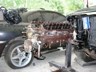
Here is the engine with most of the acessories in place. The stock A/C compressor's hose output hits the shock tower hard. I am currently looking for a compressor that has the outputs on the top and still has the serpentine pulley. I don't want to cut the shock tower.

There is still much to cover in this saga of old and new. Stay tuned!
Tuesday, September 8, 2009
Rough Harness Layout
I have roughly laid out the wiring harness with the fake foam block. Rough is the key term here. I had cut the hole in the firewall and pulled the harness through. The grommet was much to close to the end so I slid it down, away from the PCM plug. If I had it to do over, I would have done the motor swap before installing the A/C since it would have been cleaner to run the PCM harness over the plenum than under it like I have here. Hindsight is always 20/20.

I am going to cut large portions out of the '95's harness. But, to keep things simple, I want to get the car running with the harness as close to stock a possible so that I can limit the number of 'unknowns' if any problems arise. I figure I will run the A/C circuits separately from the engine harness to keep it simple. The Vintage Air setup is able to run by itself without any 'computer' control, so I want to keep that separate.
That leaves the fuel solenoid and pump. This should be straight forward. Just a line from the PCM back to the solenoid powering the pump and Inertia Fuel Shut Off switch.
More to come....
Monday, September 7, 2009
Cleaning and Prep and Painting of Block
I have disassembled the motor as far as i plan to go. I rotated the block so that the intake and exhaust ports were not exposed to my cleaning. I used Gunk and a stiff brush and removed most of the old dirt and oil from ONE side of the block. I broke up the cleaning and painting into sections so that I would not get crap into the ports. After the Gunk, I wiped the block down and then used Oxysolve to remove the rust from the cleaned side.
After the Oxy had done its work, I again wiped the excess off and then broke out the mineral spirits to clean the oxy off the block. Finally, with the block clean, I sprayed that one side with black engine paint.
I have powder coated the accessory brackets and alternator housing, along with the timing chain cover. When I pulled the timing cover off, I noticed a bunch of slack in the chain so I found an extra double roller chain and installed it along with a new seal. I also put in a new water pump since everyone knows Fords water pumps are a weak link. After sitting for a few years, the extra $50 for a new pump is cheap insurance.
I obtained a billet steel SFI harmonic balancer. Slipped right on, no problem.

You can see the Donor '95 in the background
After the Oxy had done its work, I again wiped the excess off and then broke out the mineral spirits to clean the oxy off the block. Finally, with the block clean, I sprayed that one side with black engine paint.
I have powder coated the accessory brackets and alternator housing, along with the timing chain cover. When I pulled the timing cover off, I noticed a bunch of slack in the chain so I found an extra double roller chain and installed it along with a new seal. I also put in a new water pump since everyone knows Fords water pumps are a weak link. After sitting for a few years, the extra $50 for a new pump is cheap insurance.
I obtained a billet steel SFI harmonic balancer. Slipped right on, no problem.
Saturday, September 5, 2009
Removing the Donor Engine
The 1995 GT had sustained a drivers side front impact that tore the floor pan and pushed the front wheel into the drivers compartment. This damaged the exhaust manifold on the motor and nothing else. (Besides the body of course!)
The car had an alarm and stereo system installed by the previous owner. It was not a pro job. The speaker wire used as power was the first clue. Fortunately, the main harness was not butchered in this process.
I used a SawZall to cut the exhaust away from the motor and removed the wiring and plugs and pulled the motor. I should have labeled each plug as I pulled each apart. That would have saved me some time later. I used a wiring diagram to trace the circuits so it was not a big deal.
Once the motor was out, I started to disassemble it to check for any obvious problems. I pulled the intake and accessories off. The valve covers and oil pan quickly followed. I knew that the stock 5.0 pan would not clear the steering rack so that was discarded. I used a stock 65 front sump pan and pickup.
With the covers and pan off, I could see that the 6 years that the GT had sat, had not done much to the innards of the engine. No sludge or rust. The coolant had turned to ooze though. I am putting a new water pump on just in case. With the spark plugs removed and some oil squirted in each cylinder, the crank moved smoothly.
This motor is just a place saver. I am going to use this car as a daily driver and in my spare time, I will build either a 331 stroker or maybe a 410 stroker. I am leaning toward the 331 since the shorter block will make it an easy swap. Anyway, this is for a future blog.
The wiring harnesses were pulled out and unwrapped. They were in good shape without any detectable breaks. I plan to put the computer in the glove box. The only thing I put in there is the registration and insurance cards, so this seems to be a no brainer. Also, I am putting the stock AM radio back in the dash since I have moved up to iPods. I will run a patch cord up to the console from an amp in the trunk. This will plug directly into the ipod. I never listen to the radio so why not go stealth?
More coming....
The Beginning....
This blog will document an engine swap. Specifically a 1965 Mustang Convertible will receive an EFI 5.0 from a 1995 Mustang GT. The '65 will become a mild restomod with the main exterior clue being a set of larger wheels and tires. Underneath though, some go fast goodies have been installed. This blog is starting mid stream in the project. I will endevour to detail what has taken place up to this point and then, give a play by play on the future developments.
A few years ago, a totaled 1995 mustang gt was purchased from a salvage yard. The plan was to take the efi motor and put it in the '65. Along with the wiring nightmare this would entail, a new underdash wiring harness was purchased. Along with the new harness, a JME billet gauge cluster was obtained. All new gauges and a tach!!!
Some History:
The car was purchased from a used car dealer in San Diego in 1987. It was then driven across country to where I was living at the time, Washington, D.C.
It led a normal life of going to the store and school. It was and still is Poppy Red with a white top and interior with black carpet. A stock 289 2barrel and 4spd provided motion.
In the late 1990's a mild restoration was begun with grand plans. During this time, the following parts were installed:
Currie 9inch 3.50 with large drums
Aluminum driveshaft
Tremec 3550
CenterForce Dual friction clutch
Total Control Coil Over front suspension
13inch SSBC front discs
347 stroker motor from a builder in FL
Total Control Rack and Pinion
Sanderson Headers and Flowmaster exhaust
VintageAir A/C
Three core radiator
These parts were installed and some problems immediately arose:
The steering rack rubbed on the Cobra T oil pan
The SSBC calipers rubbed on the wheels
The exhaust had minimal ground clearance so it rubbed
The motor overheated
The steering was fixed relatively easily. The exhaust was tucked up as high as it could and it remains too low for my tastes but there is only so much space to work with. The big brakes were removed and put on the shelf. The motor was a completely different story.
A crate motor builder, with a good reputation, assembled the 347 with aluminum heads, good cam, roller rockers, all the goodies. It had a 4bbl carb ontop. The motor overheated so badly that the ceramic coated headers started to discolor. All the causes were investigated. Water pump, okay. Thermostat, okay. Radiator, okay. Collapsing hoses, none found. Heater core, okay. We did a compression check and found that two cylinders were at 60psi. Finally, the decision was made to pull the heads off of the block and look. Remember, this was built by professionals. When the heads were pulled we saw that on the head gasket, the embossed word, "FRONT" was toward the rear of the car. The cooling passages were completely covered up by the gasket. But the story does not end here. In the search for information, we went back to the paperwork supplied with the motor. A dyno sheet was included but the date on the sheet listed a day when the engine was not even assembled due to the lack of needed parts. So, we got a bogus dyno sheet, and head gaskets that were installed wrong. A call to the builder said that the guy who built the motor had been fired but since we pulled the heads off, he was not liable for any quality control issues. I can understand his point, but with the gasket snafu, and the 'liar' dyno sheet, I will tell all of my friends to stay away from that builder. An easy way to avoid this builder is not to use anyone from northern FL.
With a bad compression test, the mustang was parked and left for dead in the garage. That was 2002.
A few years ago, a totaled 1995 mustang gt was purchased from a salvage yard. The plan was to take the efi motor and put it in the '65. Along with the wiring nightmare this would entail, a new underdash wiring harness was purchased. Along with the new harness, a JME billet gauge cluster was obtained. All new gauges and a tach!!!
Subscribe to:
Posts (Atom)